Tech Talk
Your GPS Speedometer Interface Module Questions Answered
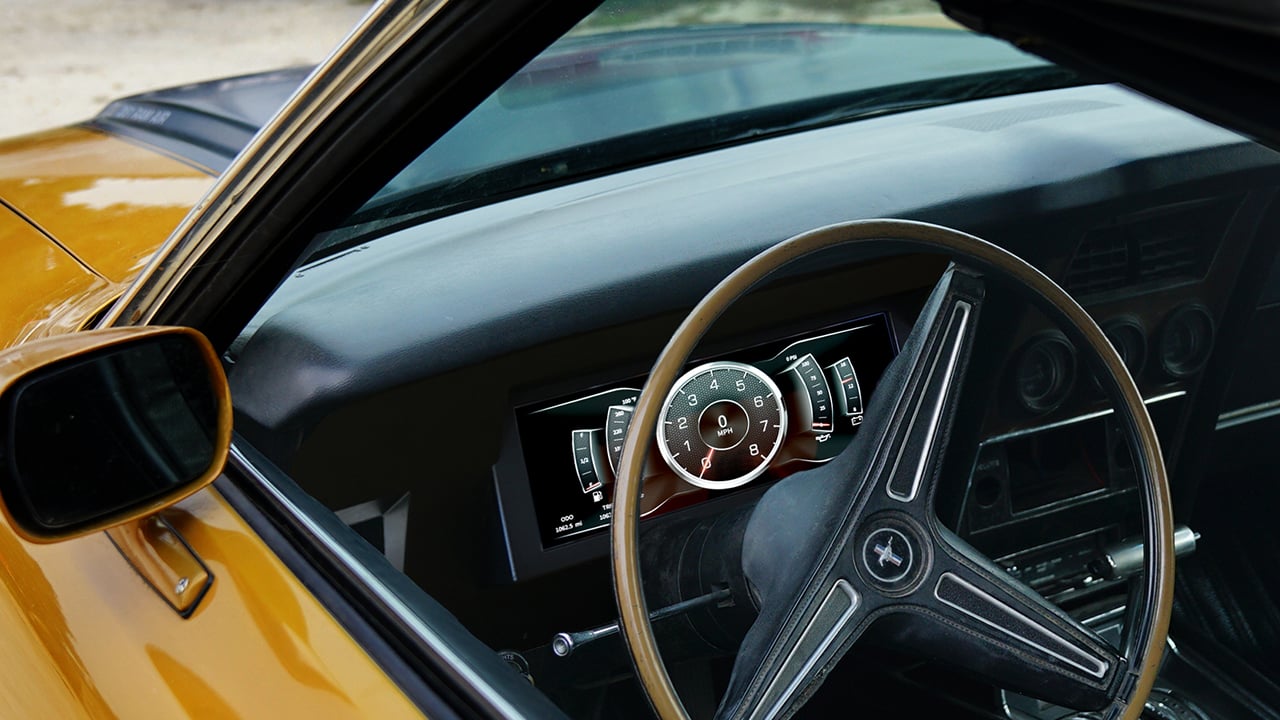
The speedometer is likely one of the gauges you spend the most time looking at. Here is some helpful information in regards to the GPS Interface Module (Model 5289):
Calibration
When using the AutoMeter GPS Module to drive your AutoMeter electric speedometer, the only time that there is no calibration required for a speedometer is when you are connecting to an AutoMeter speedometer that has not yet had a previous calibration attempt. In other words, when both the speedometer and the GPS module are new, out of the package, there is no calibration required as they are both calibrated the same from the factory. If someone has already attempted to calibrate either the speedometer or the GPS module previously, then calibration of the GPS module, to speedometer is required.
Calibrating the GPS module-to-speedometer is very easy. First, you turn the power on and then push and hold the only button on the GPS module. After a few seconds of this, the pointer on the speedometer will start to climb. The longer you hold, the faster it climbs. Stop holding when the pointer on the speedometer reaches 80. We suggest stopping around 70, then using a series of momentary button pushes. You are now done. It will time out after about 4 seconds and the pointer will go back to zero.
If you experience erratic or jumpy speedometer behavior (especially at low speeds), then power the speedometer on, and watch the LCD display on the speedometer. It will show the current PPM (pulses per mile) for a second or two, then will default to the odometer. If the PPM is quite a bit less than the factory PPM of 16000, then recalibrate both. Here is how:
- Go into speedometer calibration mode as normal (full scale).
- Push and release the button so it drops to ½ scale (as normal).
- Drive until the pulse count gets to 32000 (which is 16000 ppm), and stop driving. This does not need to be precise, just close to 32000 is good.
- Push the trip button to end calibration.
- Now, before you start driving, you need to recalibrate the GPS by pushing the button on the GPS module, going to 80 on the speedometer.
- Now, you are ready to go.
If the above is successful, but you still have a little spike or bounce at a very slow speed, then go back over the above, but double the pulse count to about 64000 pulses (32000 ppm) during speedometer calibration and then recalibrate the GPS module again. The higher pulse count is basically increasing the speed signal frequency resulting in a smoother signal.
If it is questionable whether or not the GPS module is “on”, then simply push the calibration button on the module. Does it calibrate (moving the pointer on the speedometer)? If so, then it is not only powered but also connected to the proper terminal on the speedometer.
Speaking of the GPS module being on, here is a tip. To avoid having to wait up to a minute for it to lock onto a GPS signal, you may actually connect it to battery power, rather than switched power. This applies as long as the current-existing battery draw is less than 25ma (0.025A). This needs to be checked with an ammeter, by the end user (by someone competent in using an ammeter). The current draw of the GPS module is 45 to 50ma. The “standard of the industry” parasitic draw maximum on an automotive battery is about 75ma. Of course, it is always recommended for long lengths of time such as in storage or several weeks at a time without use, to install an on/off switch and the end-user can shut it off. As long as where the vehicle is kept, it is able to capture and hold a signal, the speedometer will be ready to work as soon as you start moving.
Does the GPS seem to take a long time (as in minutes) to latch onto the signal? First, move the antenna if not already outside or near a window. Second, ask if there are any other active GPS items in use. GPS Navigation, something radio related, another speedometer (not likely, but had to throw that in there), or anything else. GPS signals can disrupt each other and compete for a signal if the antennas are too close. During earlier testing, I experienced this and was amazed how much better they responded when I separated the distance between the antennas. I was testing two interfaces, the built in GPS speedometer, and had the navigation system on, with all antennas on the dash. Nothing was happy!
The Antenna
The best location to mount the antenna is outside. Inside near any window, the top of the dash, window frame, package tray, etc. are all good spots to mount as well, but not as good as outside. The antenna is waterproof and you can paint it.
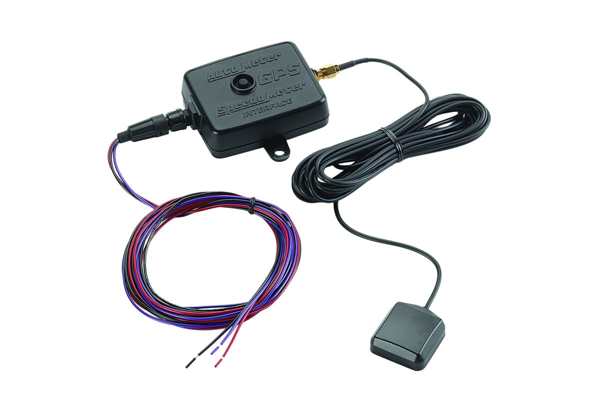
The GPS Interface Module
The GPS Sensor Module will not work with “any” speedometer. If not an AutoMeter GPS speedometer, it must be electronically driven and capable of reading a 12v square wave signal. It will not drive a mechanical speedometer. Do not wire it with an existing speed sender/sensor of any type or sort.
What applications would I use this with?
There are a variety of applications where this module can be used:
- On a vehicle where there is no existing speed sender/sensor, and no easy way to add one.
- On a vehicle that has an existing speed sensor, but due to the vehicle’s computer, transmission controller, cruise control, or ABS, you may not be able to connect another device without disrupting any of these systems.
- On vehicles where the mechanical speedometers takeoff (typically used to drive an aftermarket speed sender when converting to electric) is non functional due to a speedometer gear-related problem or malfunction.
- Or in a case where you simply want something very easy to install and wire up. Other than the antenna, it only has three wires. Power, ground, and signal out.