Tech Talk
How to Install an Air Locker Pressure Gauge
Lockers are a big investment in your 4×4. Unlike open or limited slip differentials, a locking differential is designed to lock both wheels so they travel at the same speed, which significantly increases traction in tough terrain. However, the potential downside to air lockers is that they can be prone to compression and airline issues. This can lead to air leaks, which will prevent the locker from engaging.
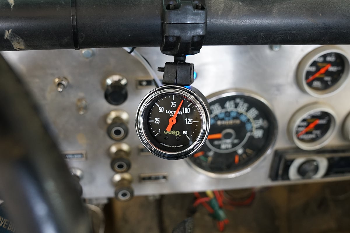
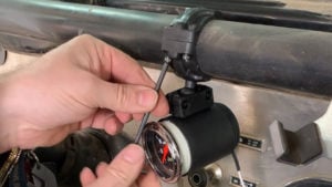
The precision mechanical Air Locker gauge from AutoMeter allows drivers to monitor onboard vehicle air used to actuate locking differentials from within the cabin. Typically, locker pressure is monitored with a remote compressor gauge that you have to get out of the vehicle to check. This is not very helpful when you are in the driver’s seat trying to navigate obstacles on the trail. Drivers can easily troubleshoot supply settings and detect loss of system pressure that could prevent proper driveline engagement and provide early warning to potential driveline damage.
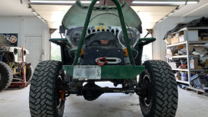

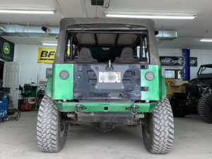
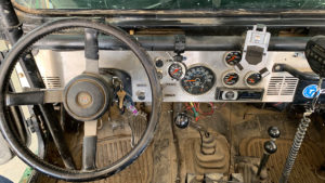
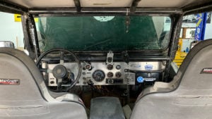
We installed this gauge in Scott’s CJ7. This Jeep is used primarily for offroading and doesn’t see a ton of on-road use. The Air Locker gauge is available in Ultra-Lite, Traditional Chrome or with Jeep branding. For this install, we went with the Jeep branded gauge.
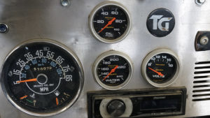
Scott had already installed Pro-Comp Oil Pressure, Water Temperature and Voltmeter gauges.
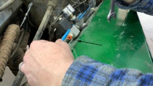
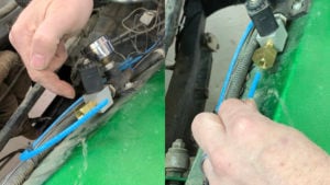
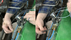
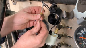
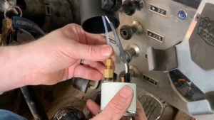
You begin by disconnecting the airline. Locate the airline on the output side of the air solenoid and disconnect it by pushing in on the orange collar and then pulling the plastic line out. Then, you can remove the fitting.
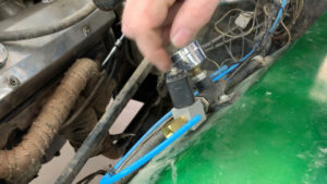
This particular kit appears to use a straight thread that is very similar to 1/8” NPT. We found that we could “massage the threads in the solenoid” to our liking with a 1/8” NPT pipe tap. We then threaded in the supplied 1/8” NPT “T” fitting. While tightening, we paid attention to the orientation of the fitting, so that the side of the fitting for the new line was pointing down, where I would like to run the new line.
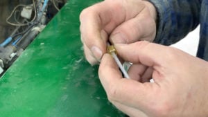
I will now re-install the original fitting with the orange lock-collar that I previously removed. This will get installed directly into the T fitting. Lubricate the threads and the rubber O-ring on the fitting. Tighten until they are snug.

I’m putting a little bit of grease on the o-ring to aid in sealing and then I’m going to thread this into the T.
Once the original fitting is threaded into the T, you can then push the original line back into the original fitting. Give it a light tug after pushing it in, and it should not come back out. It should be locked into place.
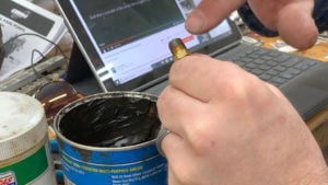
I’m going to put a little bit of grease on here. You can use Teflon paste, Teflon tape, or grease. I almost never use tape because it shreds. Pipe threads are tapered and are therefore self-sealing. This means that you do not need much sealant. In this case, we are using grease more for a lubricant than a sealant.

We will now put on the pipe thread. With a pipe thread, it is not going to bottom out. It is going to start to tighten as you thread it in. Typically you simply tighten until it is snug. After installation is completed, check for any leaks, and you can tighten a little more if needed.
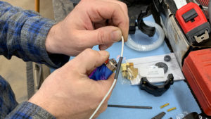
Now, we’re going to go ahead and slide on the sealing nut. We are going to take the Ferrell, which is a little compression sleeve and slide it up the line after the sealing nut. When we install this, I’m going insert the line into the fitting so that it is bottomed out. Then, I will slide the sealing nut and ferrule onto the fitting and tighten until it is finger-tight. Once we have gone finger tight, we aren’t going to go much more. It is easy to over tighten this line. We’re going to go a half turn after it is finger tight.
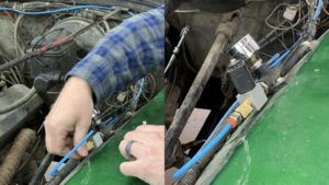
We are going to secure the line so it is not flopping around. At the beginning of the line, I am keeping a gradual bend in it because we do not want this to kink. We are purposely leaving a bit of a gradual bend here. We are also far from the engine and the exhaust, so we don’t have to worry about that. For those of you that doubt this nylon plastic tubing, it actually withstands up to 300 PSI and 300 degrees Fahrenheit.
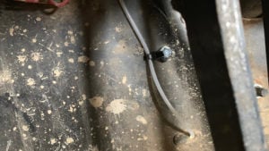
Now, we will put the line through the Jeep into the interior. The line is zip tied to the roll bar and tucked behind it.
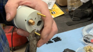
When you’re using a roll pod or any kind of mounting pod, it may be necessary to cut the studs. This does not void your warranty, as it is necessary. It is soft brass, so they cut rather easily.
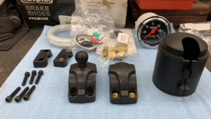

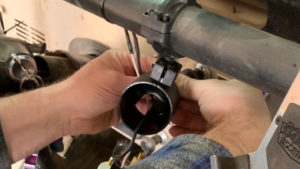
While assembling the pod, we will hold the two blocks on the cup, with the ball-end of the roll bar clamp in place. We will tighten it enough that the ball end does not fall out, but yet keep it loose enough that I can still slide the gauge in and out of the cup until completion.
We will now heat shrink a soldered connection for the lighting power wire.
Now, we will mount the gauge in the Jeep. Do not tighten the four roll bar clamp screws until you have all four started. You will then want to tighten them all a little at a time, going from one to the next, until all four are evenly, completely tightened.

I’ve already put a little grease on the male fitting coming out of the gauge, so I’m going to thread the pipe thread line fitting onto the gauge. This is our line adapter. Just like before, we were dealing with pipe thread, so once it starts to get snug, give it a little more and it’s plenty tight.
Now, we’re going to take off the sealing nut and there’s going to be a ferrule, also known as a crush sleeve. Be careful not to drop that. These get transferred onto the line. First the sealing nut, then slide the ferrule on next.
Now, I have to fish this through the back of the cup making sure I do not lose my ferrule. I’m going to bottom out the line in that fitting, bring the sealing nut back down, which brings the ferrule down, and then finger tighten the sealing nut onto the fitting. I’ll get my gauge positioned where I want it.
Just like before, we don’t want to overtighten and crush the ferrule. As soon as it is finger tight, tighten another half a turn with a wrench. Now I can start pushing everything back through where I want it in the cup.
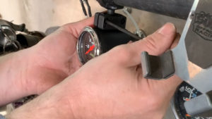
I’ll make sure the back cover is back on. Now, I can tighten the blocks that connect the cup to the ball stud, while holding the gauge in the position that you desire it to be in. You’ll want to tighten the two screws evenly a little at a time, going back and forth.
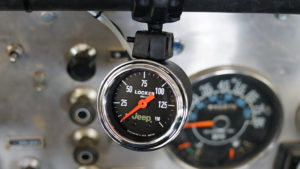
Now, the installation is complete! Properly functioning lockers could be the difference between a fun day offroading or an expensive day getting stuck. Keep an eye on your locker with an AutoMeter locker pressure gauge.