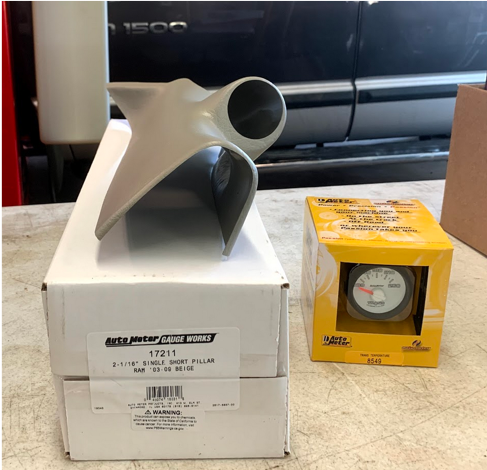
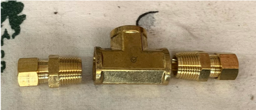
Parts used:
- AutoMeter Model #8549 3rd Gen Factory Match Trans Temp Gauge
- 17211 Single, Short Pillar Gauge Pod
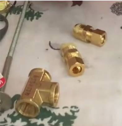
- 3/8” NPT threaded brass female “T” fitting
- Two 3/8” Male Compression Fittings
- Various 20g stranded wire
Note: We could have saved a trip to the hardware store and ordered an AutoMeter Model #2286 Transmission Temperature Manifold, though we were out of stock at the time of this install.
To Mount the Gauge
Remove the drivers side A-pillar. To do this, access the two mounting screws by unsnapping the screw covers. The screws require a 10mm socket.
After both screws are removed, you can then pull the pillar toward you and angle the top of it down, then pull it out.
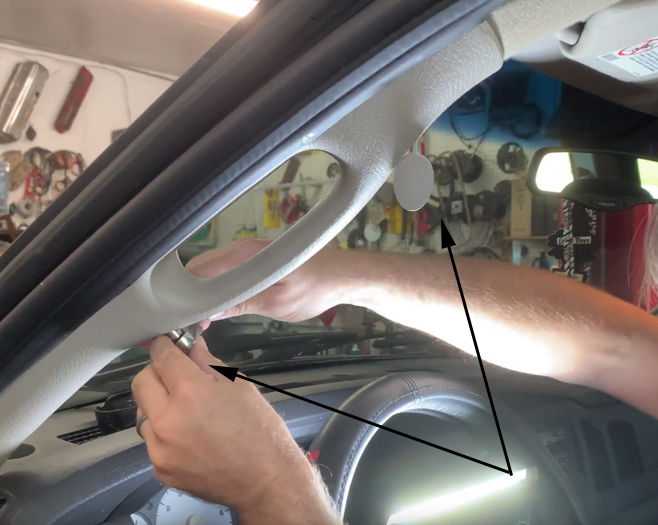

Now that the factory pillar is removed, you can test fit the new pillar cover on top of the original pillar.
At this time, you can make a mark where you want to drill a wiring pass through hole. On this particular vehicle, we trimmed the plastic molding on the original pillar to allow for better fitment of how the new pillar cover lays on top of the original. We first marked the molding with a razor blade with the new pillar cover in place, then used scissors to finalize the cut.
See photos below:
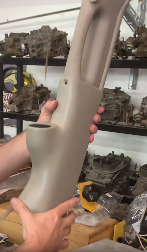


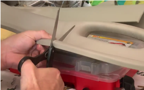
Next, you can drill the hole that you will use to pass the gauge wiring through, that you marked earlier.
We used a “uni-bit” drill bit. Some refer to them as stepped drill bits.
See photos below:


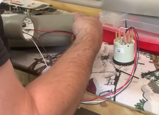
Now is a good time to pre-wire your gauge.
Here, we used red for key-on power, black for ground, purple for sender, and white for lighting power.
Now, we will feed the wiring first through the pillar cover, then next through the hole you drilled, in the original pillar. I opted to secure the wires, to keep them neat, by using small zipties every so often.
Once your wiring is passed through, I recommend NOT to push the gauge all the way into place yet. This allows extra wire during the installation, so that should you ever have to pull down the pillar again, your wiring is not stretched and tight.
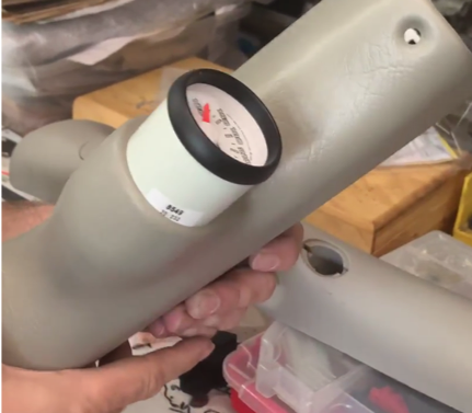

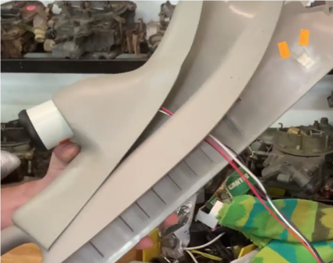
Next, I taped the end of the wires to a long, large ziptie. This will make it easier to feed the wires down through the end of the dash, while putting the pillar into place.
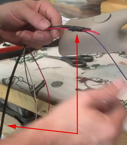

I then laid the pillars on top of the dash, and used the large ziptie taped to the wires, and fed it down the end of the dash.

I then went under the dash and pulled the wiring through and came back up top and started to place the pillars into position. First was the original followed by the pillar cover with the gauge. It is helpful if you have a partner pulling the wiring through from under the dash, while you manipulate, and position the pillars into place. Be careful not to let the wiring get in between the factory clips and the a-pillar metal structure during the installation.
TIP: There is a plastic locating dowel on the rear of the factory pillar. Make sure this lines up with the hole in the metal structure before you try to push the pillar all the way into place to engage the clips.

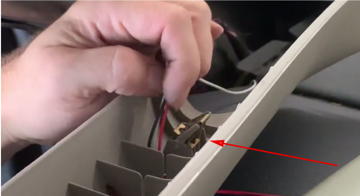
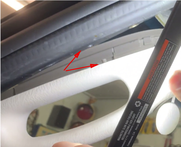
Here we pulled the gauge out, in order to take up the extra slack of wire before pushing the pillar cover into place. We will pull some of that extra slack out from under the dash before final button up, yet we will still leave enough to be able to pull the gauge should we ever need to in the future.
Once the pillar cover was in place, we installed the new AutoMeter supplied screw. To get the screw started, it required a bit of manipulating but with patience, you will get it started. We installed it hand tight, using a socket to tighten (without a ratchet).
Next, we installed the original upper screw.
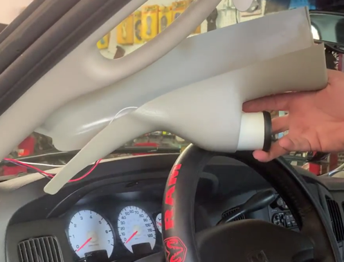

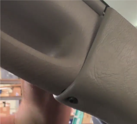
We were not a big fan of the gap that was left at the windshield, but this was an easy fix. We simply used a self-tapping screw and installed a screw in this area near the windshield.


At this point, go ahead and push the gauge all the way into the pillar and in place.
Wiring
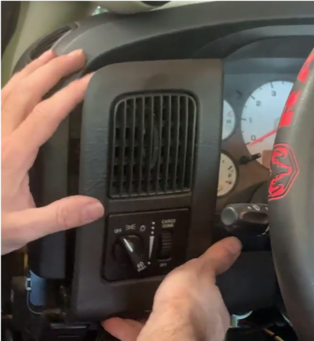
It is best to remove the cover from under the dash.
Next the bezel that holds the headlamp switch will pull out, giving you access to the back of the headlamp switch.
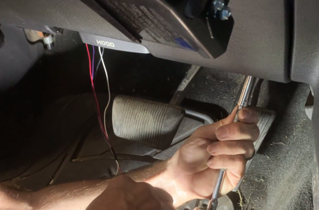

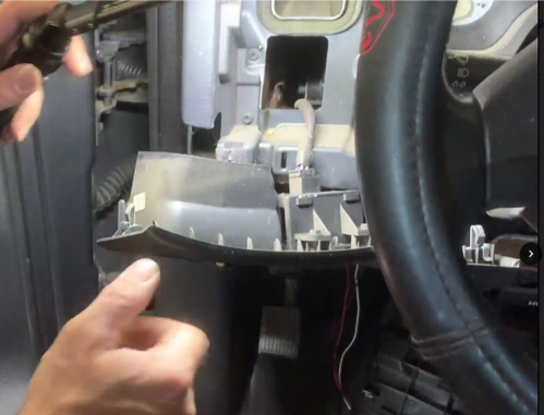
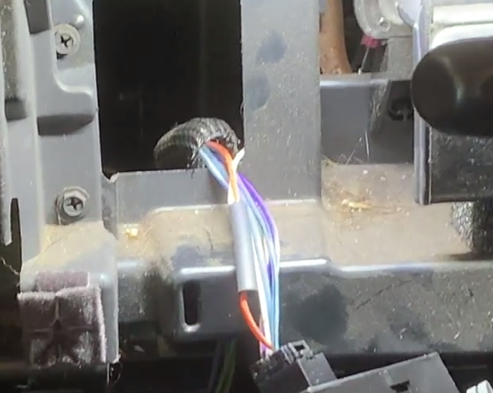
We then used a back probe pin to insert at the rear of the headlamp electrical connector and used a test light to find the correct wire. We use this method, so that you do not have to poke a hole through the insulation of your wires.
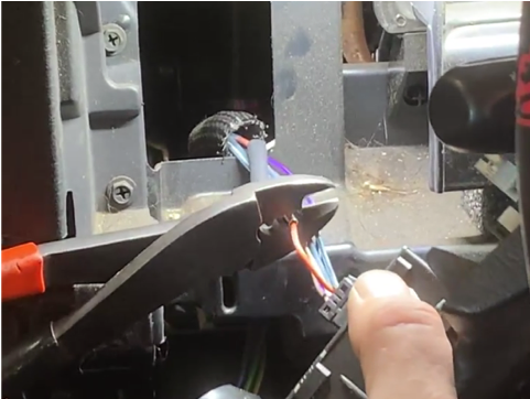
We then found the wire that turns on & off with the lighting, but also brightens & dims with the rheostat adjustment. This turned out to be the orange wire with a white trace.
We will connect our white wire from the new gauge to here.
We are using a non-insulated butt connector and heat shrink for our wire splice. After the wire splice is complete, snap the headlamp assembly back into place.
See photos below:

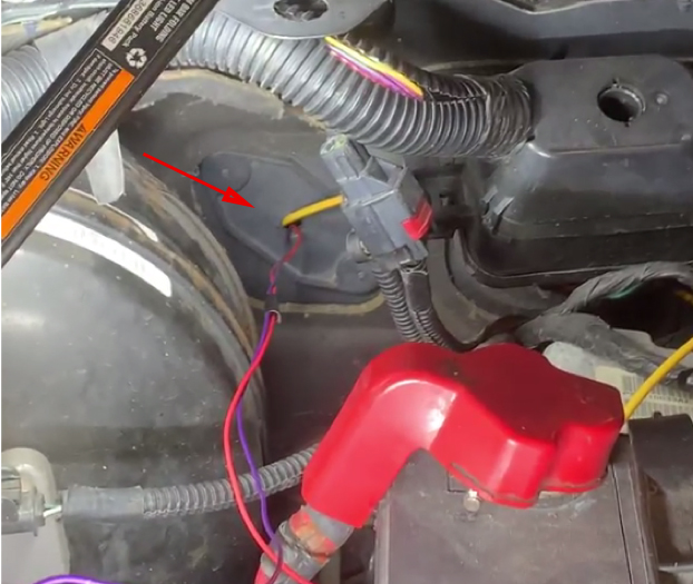
We then passed our red and purple wires into the engine bay. We used the plastic cover that is in place on automatic equipped trucks that covers where the clutch pedal to slave cylinder would normally be. This was already drilled for trailer brake wiring, which made it convenient.
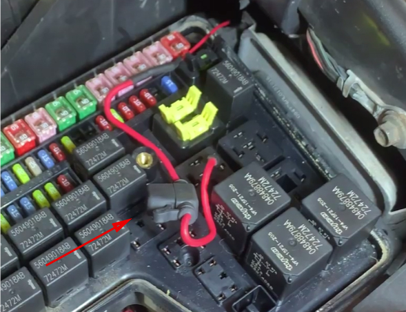
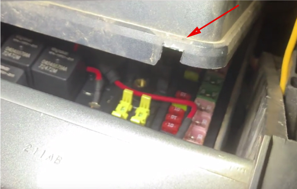
For power, we went to the factory power distribution center under the hood. We found key-on power at an unused relay location (location 68), verified with a test light, then used a ¼” male quick disconnect terminal on the end of an inline fuse holder.
We installed a 3A fuse, which is plenty for a single gauge.
Next, we will notch the power distribution cover for the wire to pass through.
See photos below:
Now it is time to prep the T fittings for installation.
- Remove the caps & ferrules (ferrules are the compression rings).
- Apply pipe thread sealant onto the pipe threads of the fittings.
- Thread the remainder of the compression fittings into the T.
- Tighten snug with wrenches.
- Apply sealant onto the threads of the 3/8”npt adapter bushing & sender.
- Install the bushing & sender into the center port of the T, and tighten with wrenches.
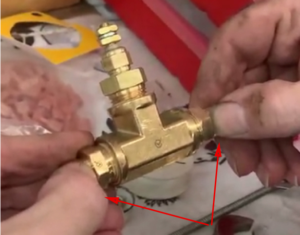
- Measure how much transmission line you need to remove. Measure from the points shown below in the picture noted by my thumbs in the 4th picture.
Please note that it is better to remove a little less than what you measures, so that the lines fit naturally tight into your T fitting set up. This way, when the nuts & ferrules are installed, they are not trying to hold everything together. They are simply connecting & sealing the lines.


Now it’s time to cut the transmission line. We want to cut the outgoing line (outgoing from transmission-to-cooler). We want the hottest possible measurement to know best what the transmission is seeing.
This is why we do not use the transmission pan, as the pan is a holding reservoir that is replenished by the returning fluid from the cooler. It will give you a cooler reading which makes your trans look like it is running cooler, but in reality is not!
We used a theory to determine which line to cut, as they were situated upper & lower on the side of the transmission. We theorized that the upper was output and lower was return, being that is would return to the pan. We later found this to be true during our trip with a loaded trailer.
We cut about 2-1/2” out of the upper line, where there was a nice straight section to cut. We used a tubing cutter and prepared to catch a little fluid.
Once cut, we slid the caps & ferrules onto the lines then positioned the T fitting in between the cut lines, which fit nice & snug.
While making sure that your line is fully inserted into the T fitting, slide the cap & ferrule down the line, and thread it onto the T. When you can’t tighten any more by hand, you wrenches to tighten the rest of the way.
I recommend tightening until the T fitting itself no longer spins on the line that you are tightening, then just a little bit more.
You do NOT want to over torque it, as it is possible to crack, or split a brass compression cap.
Repeat for the other side.
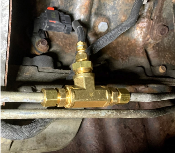
Route your sender wire to the T fitting, and install a terminal & heat shrink, to make your connection, then secure the wire along the way to keep it from moving around. Keep it clear of any moving parts, driveshaft, exhaust, etc.
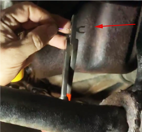
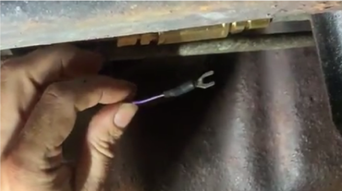
**Important note: If your transmission line(s) have any rubber or non-conductive connections, then you may need to install a grounded wire on the “body” of the T fitting. The AutoMeter sender MUST be threaded into a T fitting or temperature manifold that is grounded in order for it to function. Never install the grounded wire to the wire terminal of the sender. The sender is looking for ground through its mounting threads.
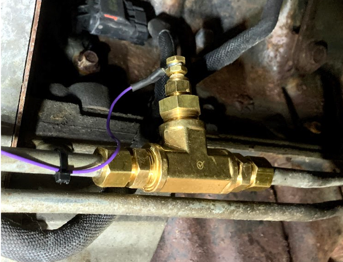
**Another important note: During our installation of the compression fittings, we ran into problems where the compression ferrule would not compress & tighten before it would literally start to protrude through the end of the threaded cap, meaning it would not seal as intended. Luckily, we were able to source better quality compression fittings. We would not have had this problem with the AutoMeter Transmission Temperature Manifold which uses much higher quality fittings.

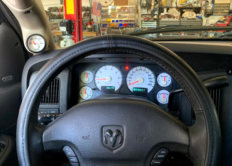

The gauge works as intended, and looks nice. It also lights up like the factory gauges.
We tested this gauge a week later on a 1,000 mile round trip pulling a loaded car trailer and the gauge responded well, showing our buildup of temperature while climbing long hills, as well as the decline in temperature while going back down the hills and onto flat surfaces. The temperature responds rather quickly in the outgoing transmission line, which is what we want to see.
