Tech Talk
INSTALLING A BOOST, PYROMETER AND TRANSMISSION TEMPERATURE GAUGE IN A 2008 FORD 6.4 POWERSTROKE
So, you’ve got a 2008 Ford Super Duty 6.4 Diesel and you want to unleash some of that hidden performance locked in your truck, but also want to have a way to monitor that engine to make sure you know what’s going on under the hood? This tech article will show you how to install the critical gauges needed to keep tabs on your modified diesel.
We realize that there is some duplication of instrumentation involved with this install, as the newer Ford Trucks carry factory Boost and Trans Temperature gauges in the factory instrument cluster. It is our experience that these gauges react slowly and provide insufficient information for the needs of modified trucks. Follow along as our Tech Department shows you where and how to install Boost, Pyrometer, and Transmission Temperature gauges on your truck.
Boost Line Installation
At the time of this writing, we are unaware of a boost source location on this truck that does not require drilling and tapping the intake elbow. The procedure detailed below discusses the methods required to drill and tap the intake elbow. If you do not feel comfortable with performing this work after reading the information below, please consult a qualified mechanic.
These trucks build 40 psi of boost from the factory. For most applications, we recommend using a 0-60psi boost gauge for this installation. For the hardcore folks, we now offer 0-100 psi boost gauges in several series as well.
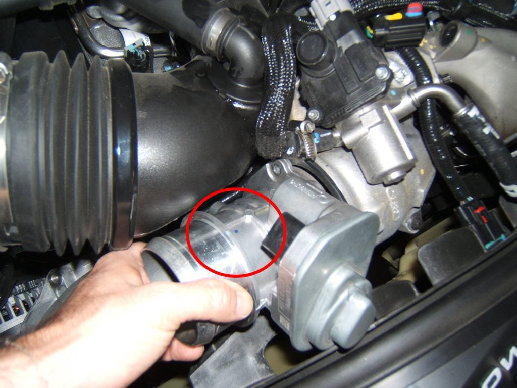
Under the hood, at the passenger’s side front of the engine bay, locate the intercooler outlet pipe where it connects to the engine brake (looks like a throttle body) on the intake elbow. Use an 11mm, deep well socket to loosen the clamps at this connection and also where this pipe connects to the intercooler in front of the radiator. Carefully remove the outlet pipe and the associated clamps and set aside.
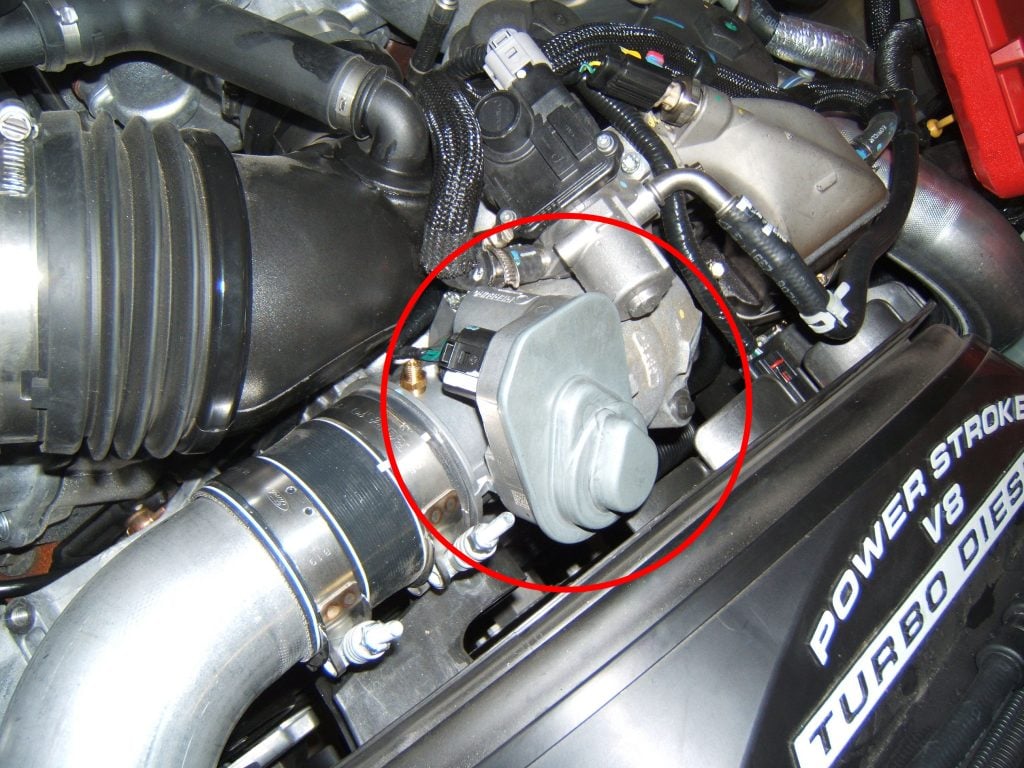
Use a marker and mark the location of where you are going to drill and tap before any further disassembly to ensure proper clearance of all components. Pay special attention to the electrical connector located on the engine brake and make sure that you have proper clearance between the boost line connection point and the connector allowing the connector to be removed. Disconnect the electrical connector off of the engine brake.

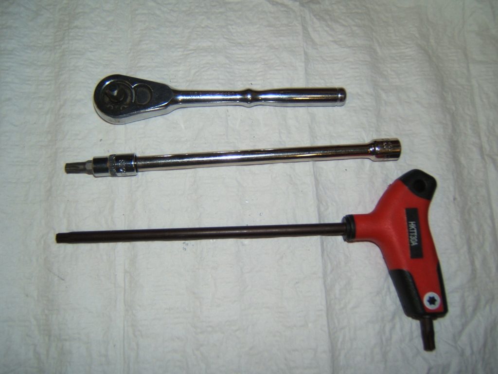
Use a T30 torx to remove the three screws that retain the engine brake. For the lower screw, you will need a long shank T30, as the socket style is too fat to fit far enough in to reach the screw.
With this part removed, you can now drill and tap a new hole for boost reference. You may use a 5/16” drill bit, and then a 1/8” NPT pipe tap. When running the tap into the newly drilled hole, it is recommended to run the tap only about halfway in, then test fit the boost line fitting. You do not want the fitting to thread all the way in and bottom out. The pipe tap is tapered, so the deeper you run the tap in, the larger the hole also becomes. Having the boost fitting thread in only a couple of turns is sufficient.
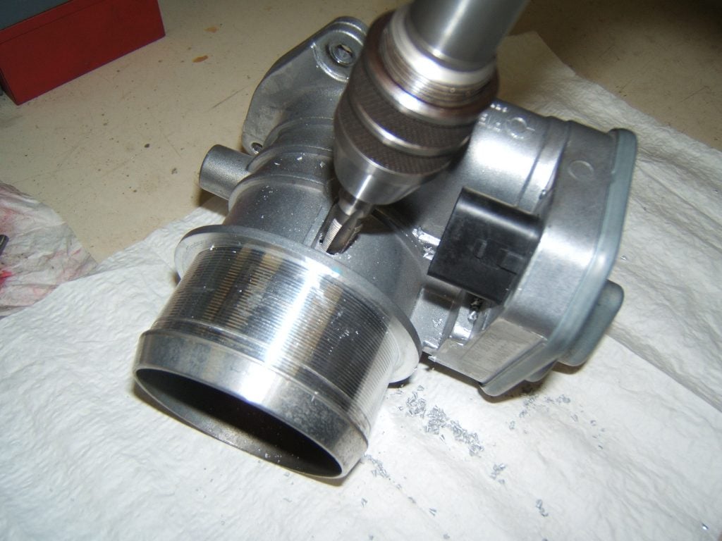
Blow out any leftover shavings with compressed air, and clean surfaces thoroughly to be certain that no metal pieces are sent into the intake assembly. Then, re-install the housing.
It helps to install the lower mounting screw into the engine brake, then carefully hold the engine brake in its location and thread in the screw with the long T30 torx. Next, thread in the other two and gently tighten all of them.
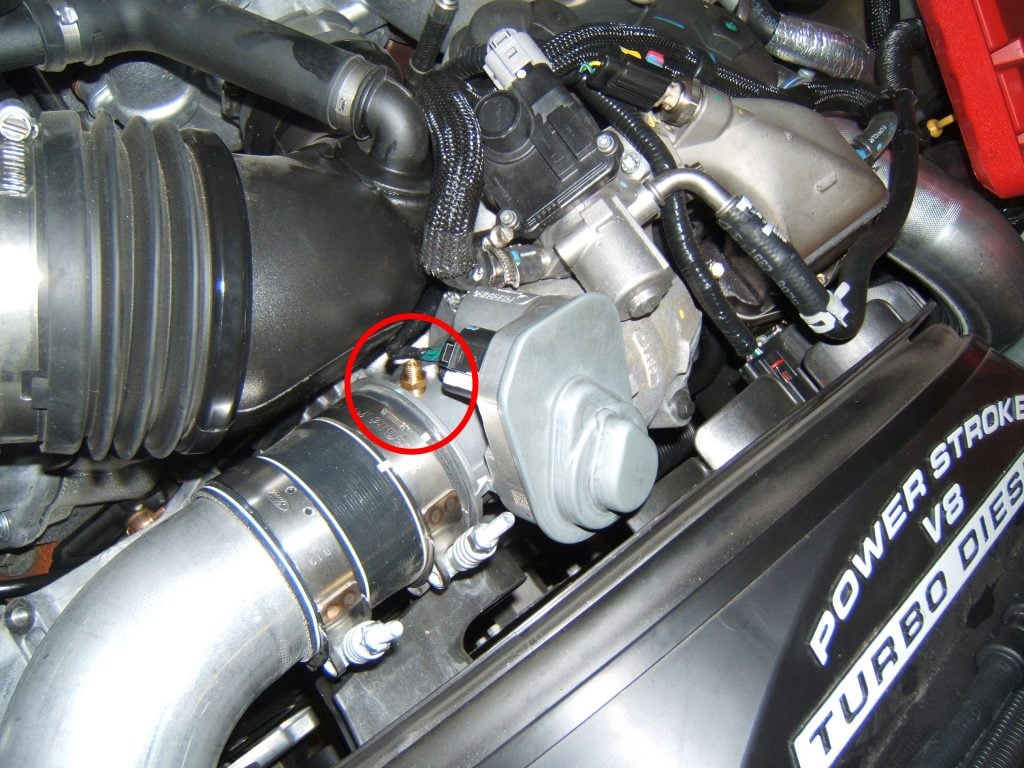
Re-install the electrical connector and then the intercooler pipe and clamps. Be certain to properly locate and torque the intercooler pipe clamps. Failure to do so can result in the outlet pipe “popping off” under high boost conditions. Do not over-tighten on the intercooler itself as the connector piece is plastic.
Transmission Temperature Installation
Look at the driver’s side of the transmission, just above the pan. You will see a threaded in pipe plug. Remove this pipe plug.
If using a short sweep electric gauge, we suggest that you use a model #2259 sender instead of the sender that came with the gauge, as the port may be very shallow. If using a full sweep electric gauge, then carefully measure the depth of the port prior to installing the sender to make sure that the sender does not bottom out and break inside of the transmission. If the port is too shallow for the full sweep sender, then you may need to use a short 1/8” npt extension.
If you are unsure of the difference between short sweep and full sweep, the short sweep electric uses a single wire, threaded terminal sender and the full sweep electric uses a 2-wire, plug in connector type of sender.
A mechanical transmission temperature gauge with a capillary tube will not fit into this port. Modification to the pan for a mechanical gauge would be necessary.
Pyrometer Installation
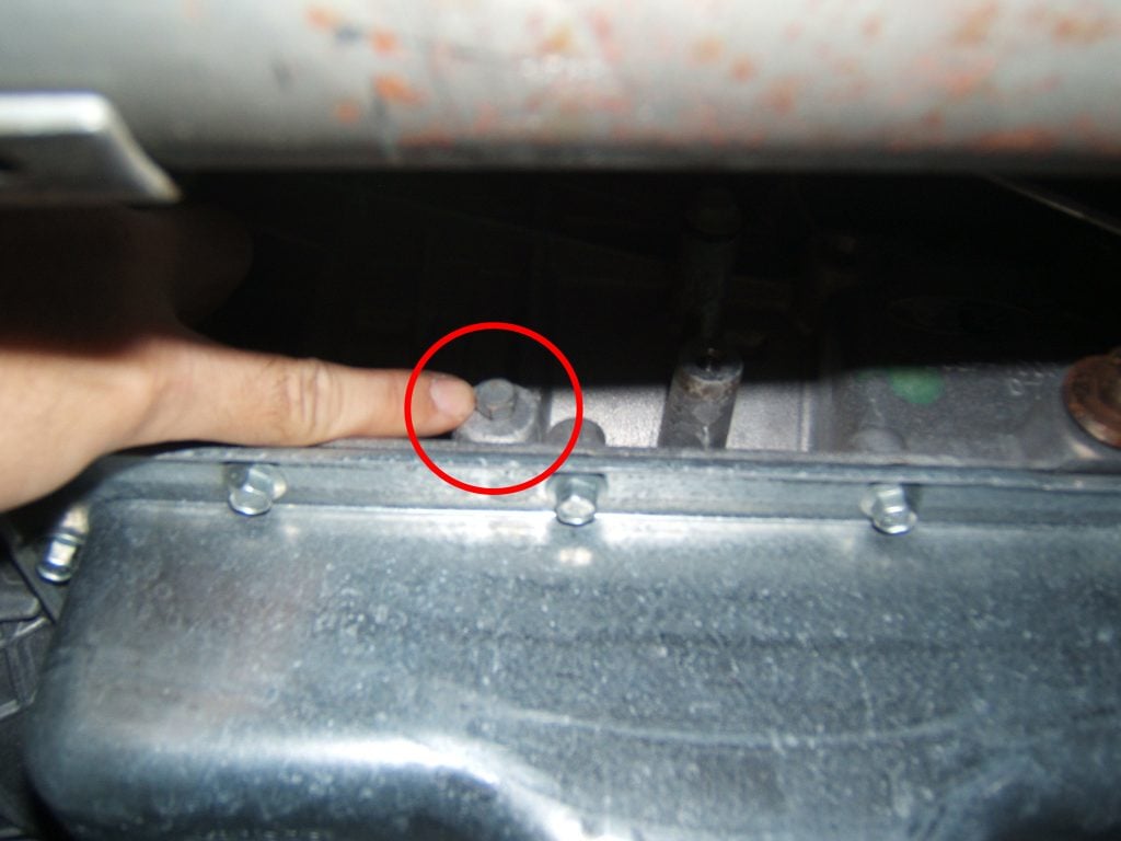
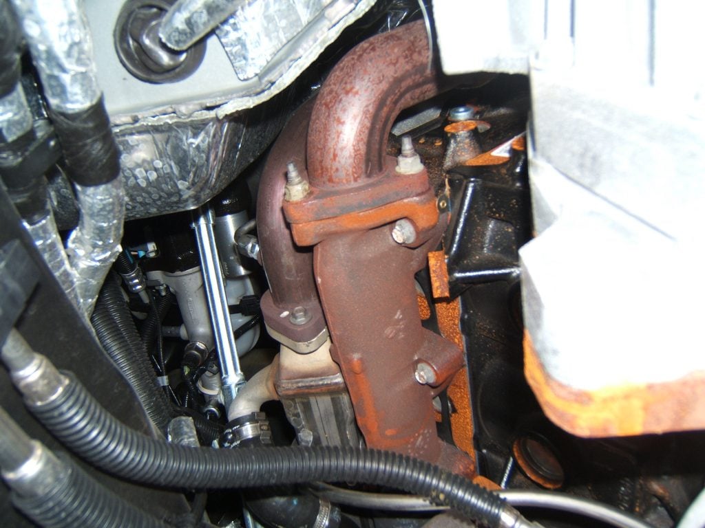
From under the vehicle, look up at the driver’s bank exhaust manifold and mark the location where you are going to drill.
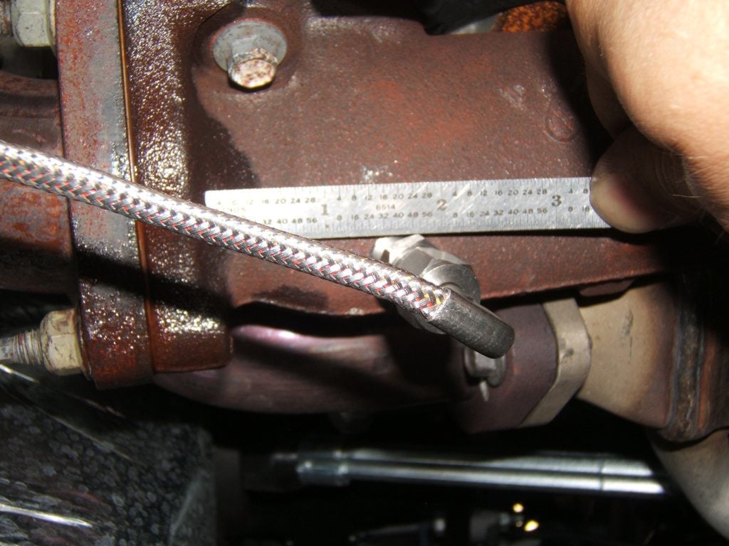
Use a 5/16” drill bit and a 1/8” NPT pipe tap. We drilled 1-1/2 inches from the flange at the rear of the manifold. Due to the shallow depth of the manifold from top to bottom, it is necessary to drill and tap at a slight angle when using a “fixed depth” probe, which is common to most of our pyrometer kits.
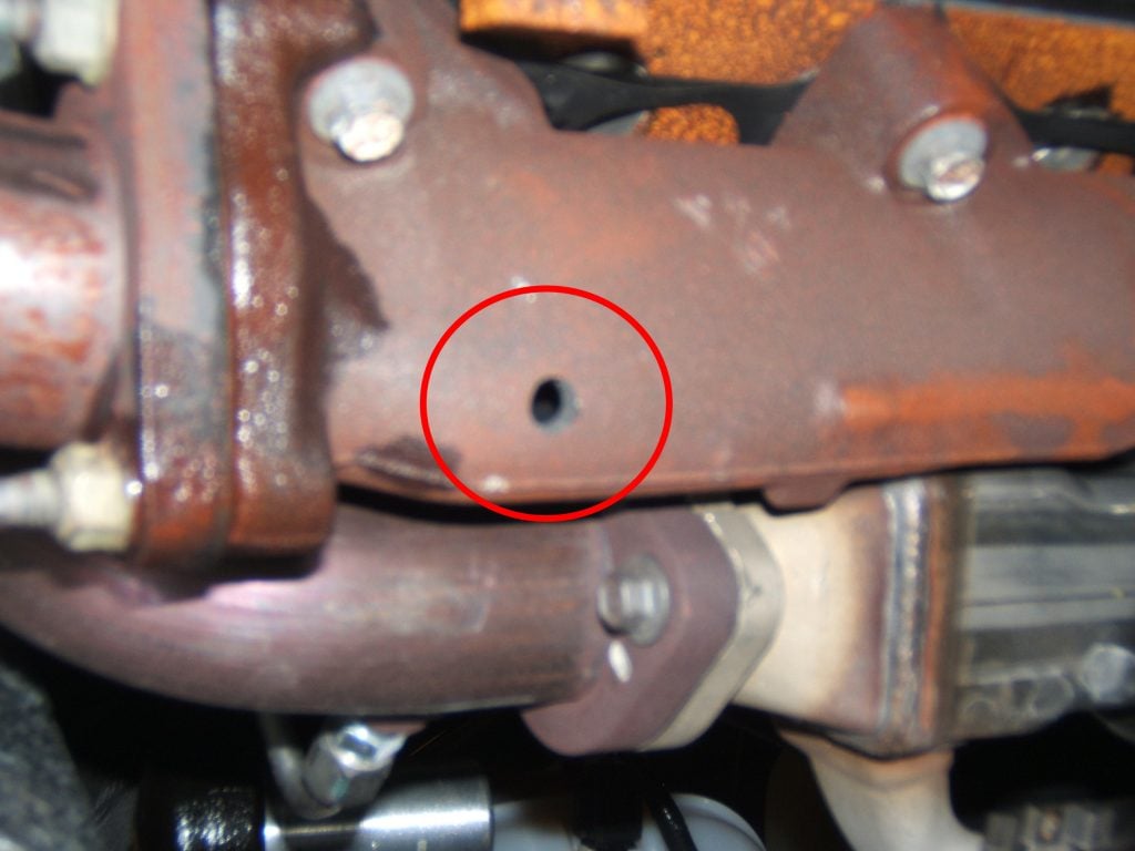
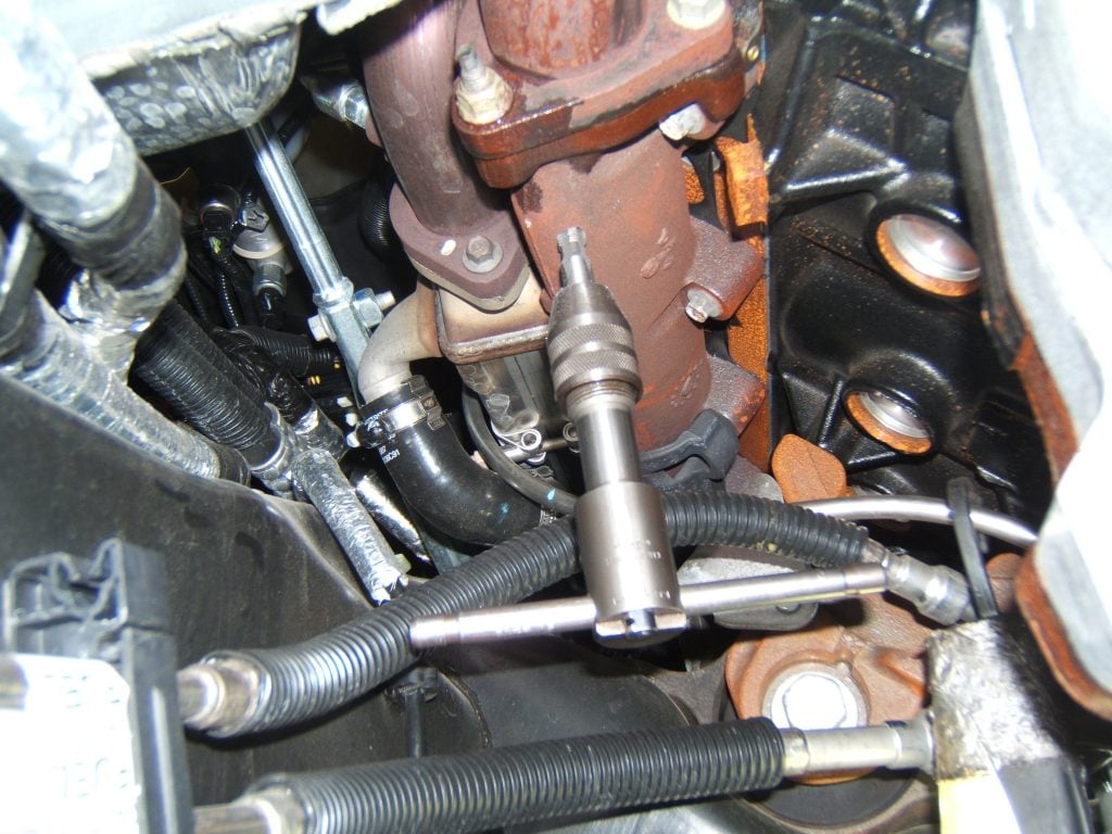
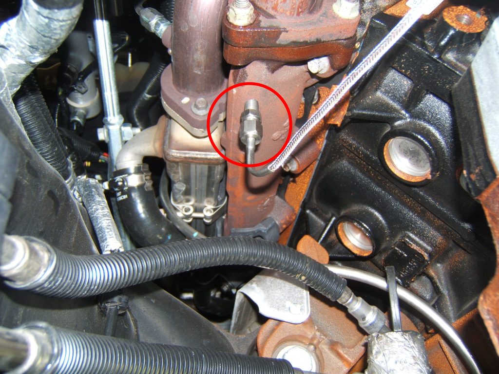
Install the supplied probe fitting and the probe.
Lighting for Gauges
Remove the vertical trim panel on the driver’s side of the dashboard containing the light and dimmer switch assembly by carefully pulling straight back to release the retaining clips. The purple wire with a gray stripe on the corner of the headlight switch connector proves to be a good dimming lighting source for the gauges.

If you are using LED lit gauges (such as our Next Generation Instruments) and if flickering is noticed during dimming, you may then need to use a model #9114 dimmer module to the park light circuit instead and use the #9114 dimmer to control the brightness of the LED gauges.
Finish installation as per instructions provided with the products being installed.
Pillar pods are molded in Black Revotech plastic from the factory. We employed a body shop to paint the pillar mount shown in this picture to match the factory interior colors of this truck.