This time we’re taking an in-depth look at how to hook up what are considered by many tuners to be essential gauges on an 07 Subaru WRX STi. We also examine the installation of the #20018 Center Dash Pod and include some helpful tips for installation.
Though this install was performed on the 07 STI model, much of the information provided below will prove helpful to owners of the Impreza, WRX, and STI models from prior years as well.
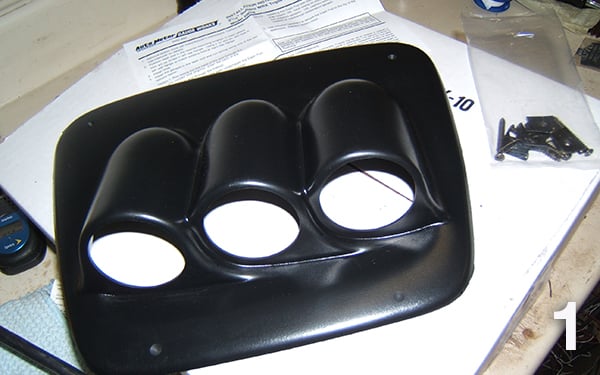
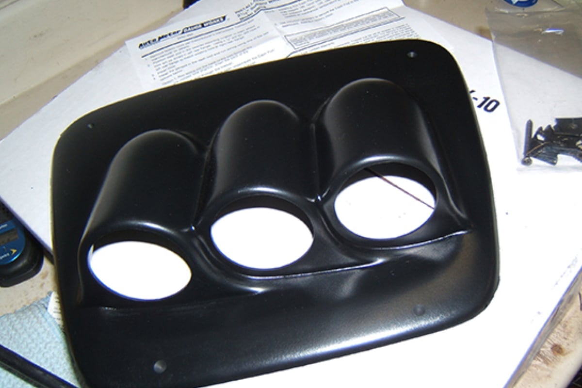
Important! First things first, after you open the hood, Disconnect one of the battery terminals before moving on with the rest of the install! On this particular vehicle, we’re installing a Triple Dash Pod #20018. This unit replaces the clock located in the center dash of Subaru Impreza vehicles from 2002-2007 and allows the addition of three, 2 1/16″ to be installed angled towards the driver for optimized viewing.
In the steps that follow we’ll take a look at how to remove the clock panel and the steps required to install the new gauge pod assembly.
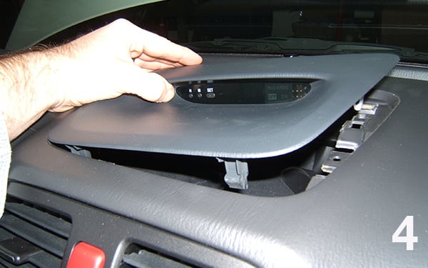
Remove the factory clock pod. This piece snaps out, pull up sharply at the front of the pod (towards the windshield) to take loose.
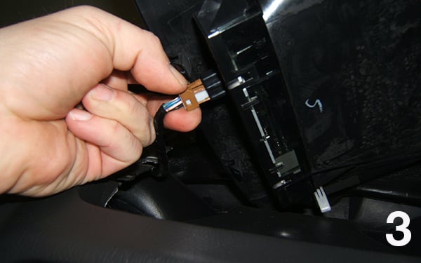
Unplug the wire harness connector from the clock and secure it out of the way with a piece of tape to prevent dash rattles. You will not be using this connector/harness for this install.
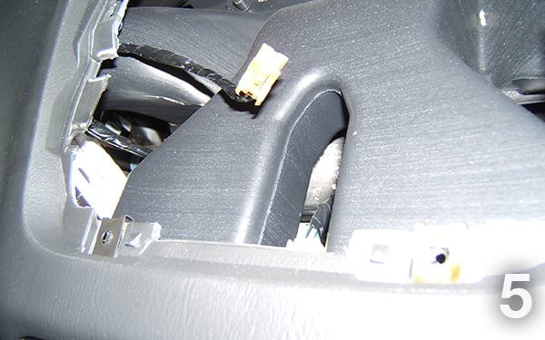
View of the dash with the clock piece removed and harness unplugged.
Install 3 of the four included screw clips in the 3 corners where there are already holes.
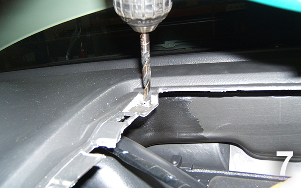
For the 4th, you will have to mark the location and drill the hole.
To mark the location, use a 1/8” drill and drill through the pod at the 4 corners where the pod has already been pre-drilled. Partially thread in the 4 screws that were included with the pod, into the pod. Set the pod in place and carefully position the pod and screws and start to screw the pod down with the 3 screws that already have holes with clips.
Remove the 4th screw, and use a pointed pick, or screwdriver and scribe the location of where the 4th hole needs to be. Remove the pod, now.
Using a right-angle drill, with a 1/4” drill bit, drill the required hole for the 4th screw and clip. A standard drill likely will not work due to the close proximity of the windshield. Install the 4th clip, then test fit the pod with all 4 screws.
Pre-wire your gauges in the pod, but only slide them in part way, and leave enough slack in the wiring, or tubing so that the gauge can be slid in and out if needed after or during pod installation.
Route the wires from the gauges down past the ductwork, favoring the drivers’ side. You can then reach up from underneath the driver’s side of the dash and grab the wires to gently pull them down the rest of the way.
You may now mount your pod, and tighten the screws. When you tighten the screws, you do not want to tighten until they stop turning, otherwise, you risk damaging or warping the pod.
Now that this is done, let’s move on to locating and making connections under the hood for the Boost/Vac, Oil Pressure, and EGT/Pyrometer gauges.
Boost/Vac Installation:
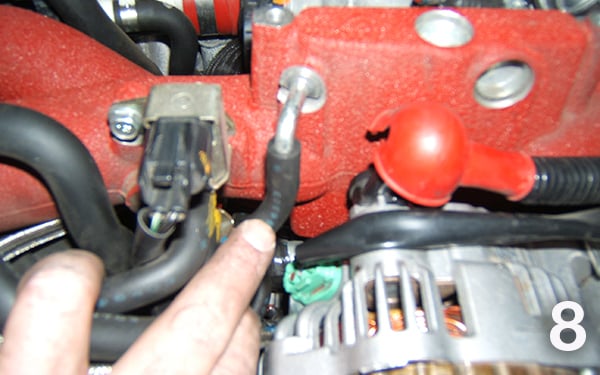
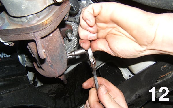
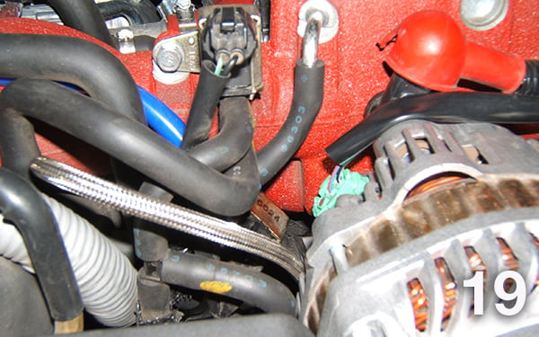
On the front of the intake manifold, you will find a vacuum line near the rear of the alternator.
This is a 1/4” I.D. hose and will require the purchase of a 1/4”, 3-way vacuum T from a local auto parts store. The 3/16″ x 3/16″ x 1/4″ T included in the kit is too small for mounting in this location.
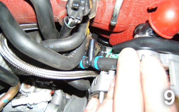
Route boost/vacuum line accordingly. If you remove this vacuum line as we did for the installation, make sure that you reconnect it!
EGT / Pyrometer Installation:
With the vehicle raised, remove the plastic aeropan from under the vehicle that goes from the bumper, rearward, and side to side. This gives you access to the exhaust manifolds from under the vehicle.
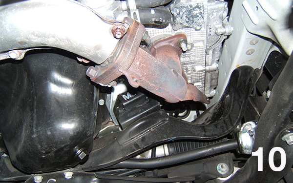
This image shows the location of the driver’s side cast iron exhaust manifold that we will be using for a probe mounting location. Here we’re looking from the front of the car towards the back. Note the oil pan and filter in the central and left locations of the image. Note: This image was taken with the plastic aeropan and exhaust manifold heat shielding already removed.
On the drivers’ side manifold, you will need to remove the 2-halves of the heatshield first (already removed in this picture). Then locate this raised boss on the manifold that you can drill and tap.
Use a center punch to mark the center of the boss and help prevent the drill bit from walking.
Drill through the previously marked boss on the manifold using a 5/16” drill bit. We opted to perform this operation on the vehicle.
If this makes you uncomfortable you may also remove this piece from the car by removing 5 14mm nuts that hold the manifold in place.
Next, follow through with a 1/8” NPT pipe tap.
Install the included pyrometer probe fitting(s). Carefully mark the location on the heat shield where you have drilled the hole, so that you can drill the heat shield to match, for the probe to come through. After installing the retaining nut for the probe we put a thick layer of grease on it and placed the heatshield back in place. The grease transferred the location of the nut to the heatshield. We used a common, stepped drill bit and drilled a 3/4” hole in the heat shield. Install the probe.
Re-install the heat shield, then the plastic aeropan cover.
Oil Pressure Installation:
There are a couple of options on how to obtain an oil pressure reading from this engine. In this example, we opted to use the factory oil pressure port, that holds the low oil pressure warning light switch. Note: When removing this switch, you will lose function of the factory warning light. It will not however cause a check engine light or code on the vehicle computer.
To access this port, make sure battery power is disconnected. then remove the battery wire from the back of the alternator, and remove the alternator from the vehicle.
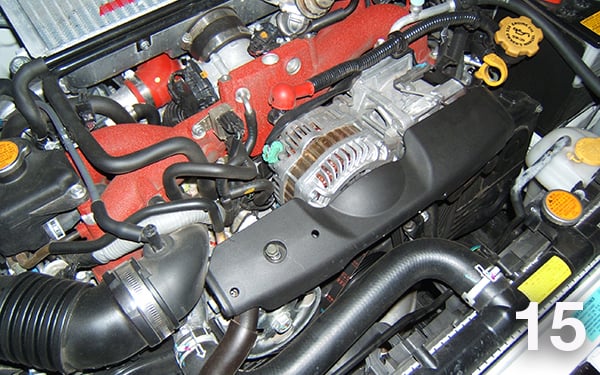
Here’s the factory oil pressure switch as viewed from the passenger’s side front of the engine bay before we begin disassembly.
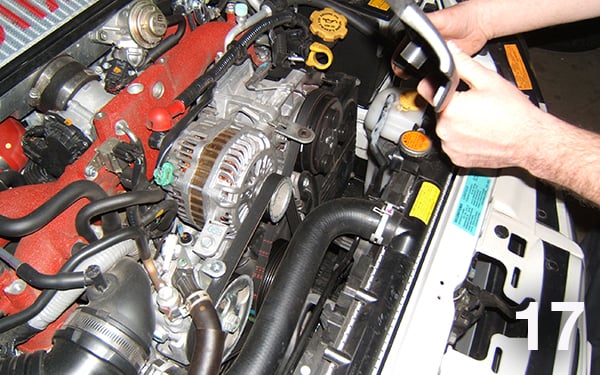
Next, remove the plastic alternator shroud assembly, and consult the Subaru factory service manual for the proper steps required to remove the alternator.
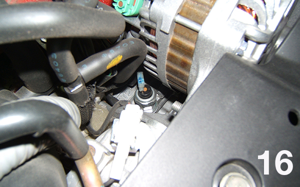
Here you can get a better look at the factory oil pressure switch with the alternator out of the way.
Use a 15/16” socket to remove the factory oil pressure switch. Zip tie the harness to nearby harnesses/hoses to keep it from vibrating about. With the switch removed you will not be continuing to use this harness.
Because of the proximity to the alternator in this particular case, we opted for a remote mounting location for the oil pressure sender.
You will need a #2269 adapter for this location. We used AutoMeter #3227 stainless braided line kit in order to remote mount the sending unit.
Install the adapter in place of the factory pressure switch. Install the line kit onto the adapter, and route to the passenger side of the engine bay.
Reinstall the alternator and the alternator shroud and reconnect the battery wire to the alternator. Here’s a shot of the braided line and adapter installed with everything back in place.
Thread the sender for the oil pressure gauge into the end of the line, and mount the sender to the strut tower, or inner fender.
Note: If you are using a mechanical oil pressure gauge, you will then run your oil pressure line that came with your gauge straight to the adapter that you installed into the engine.
Here you can see where we’ve remote mounted the oil pressure sending unit using a rubber coated performance line clamp between the airbox and the passenger’s side strut tower. This picture is taken looking over the passenger’s side fender.
Note: It is normal to see oil pressure in excess of 100 psi when the engine/oil is cold.
Gauge Power: You may use a fuse tap, or add-a-circuit kit and use power from fuse #11. This fuse also works well when using an electric vac/boost gauge, which requires power during cranking of the starter as well.
To access the interior fuse box, remove the coin/pocket door on the lower left side of the driver’s side dashboard.
This picture shows the add-a-circuit kit installed in two locations. The power is circled for your reference. The other add-a-circuit is for gauge illumination which we’ll cover next.
Gauge Lighting: We weren’t able to locate a suitable panel illumination wire for dimming on this vehicle. Since we were using LED-lit gauges, we were able to use the #9114 dimmer module, and we used a fuse tap at fuse #12 (the illum fuse) for our lighting power.
If you are using perimeter incandescent lit gauges, then you may need to use an aftermarket dimming rheostat from a company such as Painless Wiring (www.painlessperformance.com). Or if you do not want to be able to dim them at night, you can then go straight to fuse #12.
We mounted the AutoMeter #9114 dimmer module in the coin door located in front of the fuse panel for easy access and adjustability.
For ease of removal and access to the fuse box, we installed a 4-pin connector from Radio Shack in order to allow the fuse box door now containing our dimmer to be totally removable from the dash assembly.
Route wiring and finish gauge connections as per the product instructions. Reinstall battery negative cable, start the vehicle and check for leaks and proper gauge operation.