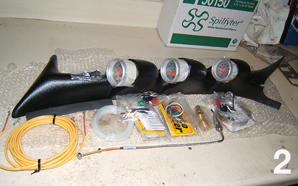
This tech article supplements the instructions included with the AutoMeter #7075 Diesel Kit and gives complete details on what you will need and how to install the critical gauges needed to keep tabs on your modified diesel.
Important! First things first, after you open the hood, Disconnect one of the battery terminals before moving on with the rest of the install! Suggested Items Required to Complete Kit Installation:
– White, 18g automotive wire (for gauge lighting), about 4’
– Black, 18g automotive wire (for gauge ground), 3 to 6’ depending on where you choose to ground your gauges.
– Red, 18g automotive wire, (for gauge powers), about 4’
– Any other color of 18g, automotive wire (for trans temp sender), about 6 to 8’
– Little Fuse (or equivalent) Add-a-Circuit kit for mini fuses to tap into the interior fuse box for power.
– (3x) Female spade (“quick disconnect”) terminals to fit 1/4” spades and the 18g wire (mentioned above) for the trans temp gauge.
– Assortment of different sized ring terminals for 18g wire.
– Either 18g butt connectors or solder and heat shrink.
– 1/4” Vacuum “T” fitting, available at most local parts stores.
– 2259 AutoMeter temp sender for trans temp gauge if mounting in the transmission test port on the drivers side of the transmission.
– Variety of zip ties (for securing wires).
– Heavy, or thick grease to use on drill and tap when drilling and tapping the exhaust manifold.
– Electrical tape.
Suggested Tools Required to Complete Kit installation:
– Wire crimpers
– Wire strippers
– Soldering iron (optional)
– 3/16” drill bit (for drilling pillars for pod push pins/rivots)
– 5/16” drill bit (for drilling exhaust manifold for EGT probe)
– 1/8” NPT tap, and tap handle (for EGT probe).
– Drill
– Side cutters (or equivalent) for cutting boost hose).
– Standard & Metric 1/4” & 3/8” drive socket set.
– Standard & Metric wrench set
Wiring & Pre-Installation:
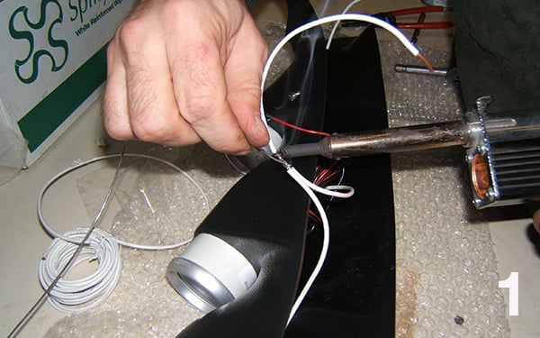
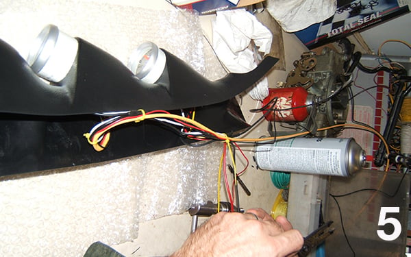
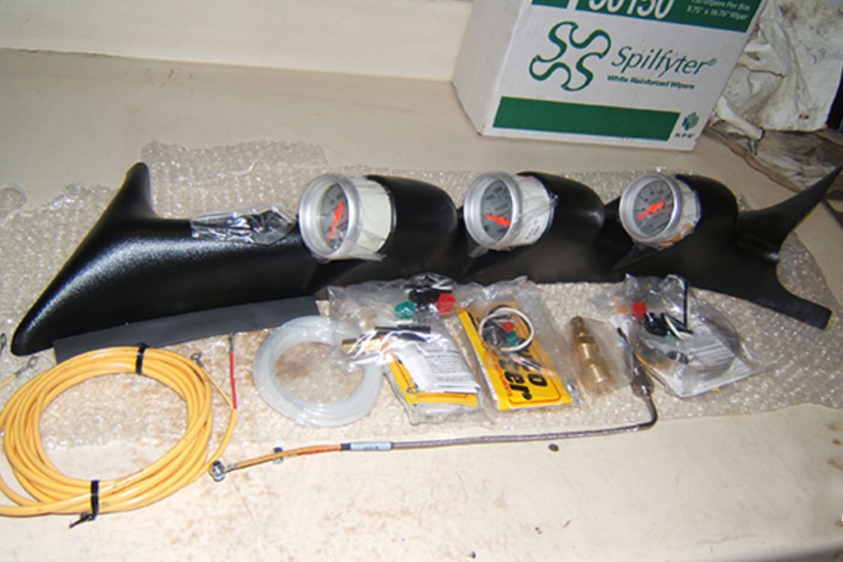
It is a good idea to pre-wire the pod on a clean & clear workbench. Slide the gauges out of the pod, so that when you wire the gauges and assemble everything, you have extra wire behind the gauges in case you ever need to service lighting or anything else related to the gauges. Wire the light powers together to form one common lighting wire.
Wire, the grounds for the lighting together to form one common ground wire for the lighting.
Wire the grounds for the gauges together to form one common ground for the gauges (these are recommended to be grounded separately from lighting).
Wire the powers for the pyrometer and the trans temp together to form one common power for both gauges.
Run a wire from the “S” (sender) terminal of the transmission temperature gauge. You will use the female slide on terminals for the trans temp gauge.
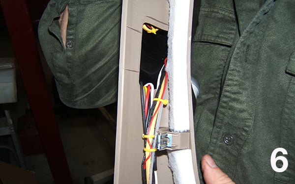
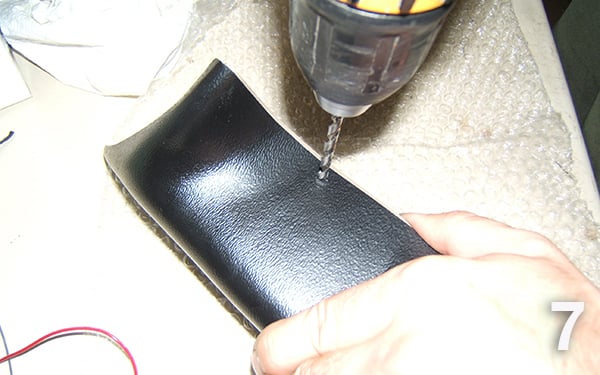
Install the pyrometer leads onto the gauge. Pay attention to the ring terminals on the yellow EGT wire. The end with the larger terminals goes on the gauge Install the boost gauge line adapter to the gauge, then carefully unroll the boost line. Slide the nut onto the line, then slide the ferrule onto the line. Insert the line, ferrule, and nut onto the adapter and tighten. Do NOT over-tighten as this will over-crush the ferrule and potentially pinch off the line, or break the line. Neatly arrange the wiring together, and use zip ties to bundle them together. Route the (now bundled) wires through the lower grab handle hole of the original pillar. Carefully fit the new pillar onto the original pillar, with the wiring exiting through the lower grab handle hole of the original pillar. Once you have the new pillar in the desired location, hold the two pillars together and have an assistant drill (6x) 3/16” diameter holes in various locations. These holes are used to install the rivets (push pins) that hold the pillars together. We suggest that you evenly space them, 3 along each side, toward the edge of the pillar.
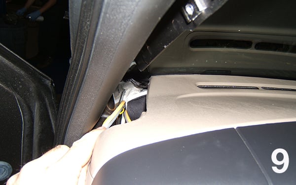
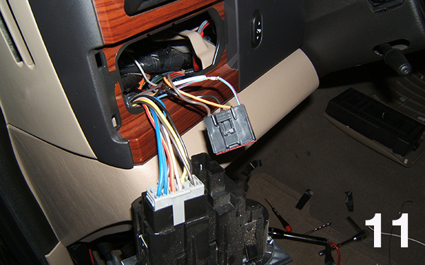
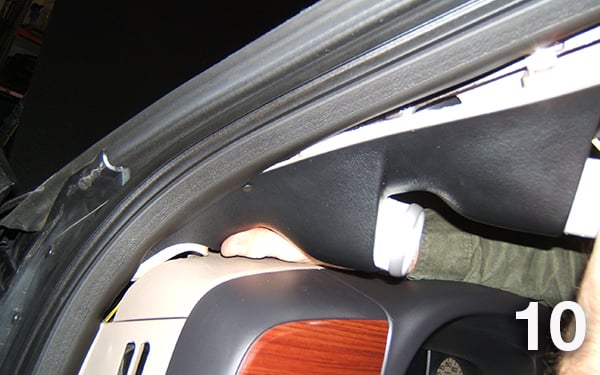
Push the rivets (push-pins) through the drilled holes. It is also recommended that you push each push-pin through after each hole is drilled to prevent mis-drilling due to the pod shifting on the factory pillar cover. While getting ready to install the pillars into the truck, have an assistant look up, under the dash while you start to feed the wires down through the opening between the dash and where the pillar will go. There is plenty of room for the wires. The new gauge pillar mount will be a snug fit, going back in. Take your time, and make sure that the clips all align from the original pillar to the metal pillar structure before pushing the pillar assembly fully into place. While under the dash, reach behind the headlight switch and push it from behind, out of the dash. Locate the blue wire with a red stripe. Strip about 1/4” of insulation off of the wire and wrap the bared end of the white wire coming from your pillar to this wire. Solder it, then tape it, to insulate it.
Push the headlight switch back into the dash.
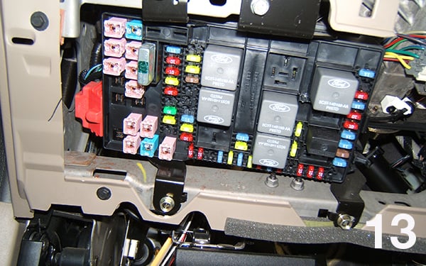
Remove the lower dash panel to access the interior fuse box, by pulling straight back. Next, remove the cover off of the fuse box. Along the far right side of the fuse box, at the bottom, you will find a 15a fuse, which is also the factory Instrument Cluster fuse. Remove this fuse and install it into the Add-a-Circuit kit. Install a 3a fuse into the wire-side of the Add-a-Circuit kit. Crimp or solder your red wire coming from the pillar to the red wire on the Add-a-Circuit kit.
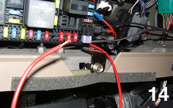
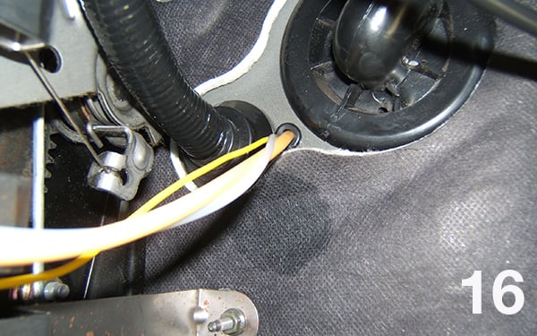
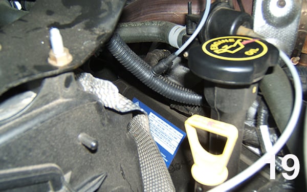
You will need to carefully trim a small pass-through in the side of the fuse box cover for the wire to pass through when the cover is installed. To the right of the fuse box, you will find several factory grounds. Choose any two. Run one ground (black wire) from the pillar to one, and run the other ground (black wire) from the pillar to another. You may use crimp on ring terminals for this. After these are hooked up, your gauge lights and gauge powers should now function. Choose a suitable location to the left of the steering column and drill a 3/8” diameter hole in the firewall (see image at right for suggested location), and insert a rubber grommet. Be careful not to drill into any existing wires or components on the other side.
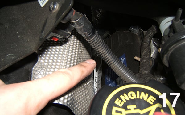
Begin passing the pyrometer leads, boost line, and trans temp wire through the grommet. Have an assistant on the other side “gently pull on the wires. This may be a tight fit, so using silicone spray, WD-40, PB Blaster, or equivalent (sparingly) on the wires will make them slide through the grommet much easier. Route the boost line to the passenger side, to the MAP sensor, which is mounted on top of the heater-a/c box on passenger side of the engine bay. Be sure to route the boost line so that it does not become melted from heat from the turbo.
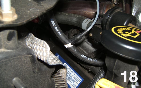
Peel back the plastic covering from the hose that goes to the MAP sensor. Use a pair of side cutters and cut the hose in half. Slide both ends of the cut hose onto the two opposing ends of the separately purchased 3 way 1/4” T fitting (Supplied T-fitting not compatible with this boost line location).
We recommend using Super glue, or Weather strip adhesive on the boost line, then slide the boost line into the supplied, black rubber boot. Slide the boot onto the existing leg of the T. Recover the MAP sensor line with the plastic covering to finish the T-fitting installation. Route the pyrometer leads away from any hot sources, or moving parts (such as the steering column), and down to the underside of the vehicle in the area of the drivers’ side manifold.
From under the vehicle, mark a location toward the rear of the manifold, and drill a 5/16” diameter hole. Some installers prefer to grease the bit to help capture metal shavings. Be careful as the shavings may be hot, and you do not want to get these shaving in your eyes! Safety glasses are a must!
After drilling the hole, dip your 1/8” NPT pipe tap into some grease, and run the tap at least half way into the hole.
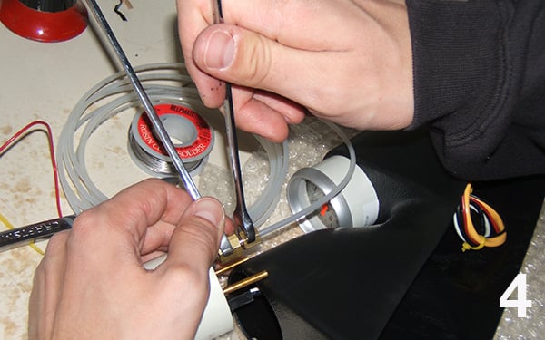
Next, install the double male fitting that came with your probe. The fine threads-side of the fitting installs into the newly drilled and tapped hole.
Slide the probe into the fitting, and tighten the nut.
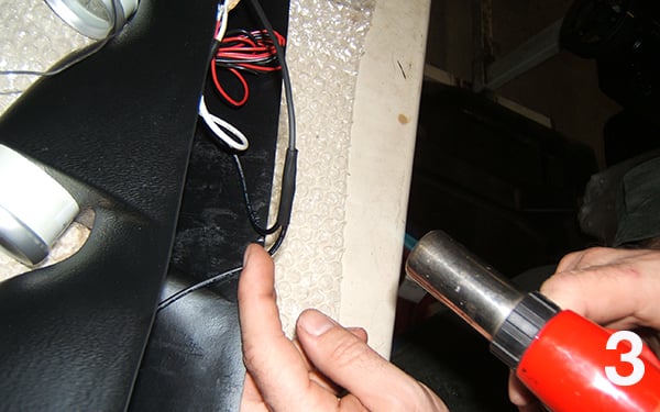
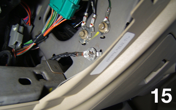
Slide the supplied probe heat shrink onto the probe leads.
Hook the yellow probe wire to the yellow probe lead, and then the red to red. Use the supplied nuts and bolts.
The yellow EGT probe wire may need to be folded due to the difference in length. Heat the heat shrink over the connections.
Securely, bundle up the excess probe wire length. Do not cut, shorten, or modify the EGT wire.
Run your transmission temp sender wire along the same path as your EGT wire, ending near the drivers’ side of the transmission.
You will find a threaded in pipe plug, just above the trans pan. Remove this plug.
Install the new, shorter #2259 (shown at the right of image vs. included & longer #2258) sender into this port. ** The reason for the shorter sender, is that the longer one may bottom out in this port. If you choose to use the longer sender, you will then have to modify the pan to accept a 1/8”NPT thread size.** Crimp or solder a ring terminal onto the end of the trans temp sender wire, then install on the trans temp sender. You are now ready to start the truck!
Inspect for leaks at the boost line connections (this can be done by mixing dish soap and water in a spray bottle then spraying the combination on the area to be checked. If you observe bubbling you will want to check tighten your connections. Also, be sure to inspect the trans temp sender mount as well. When the truck is put under load, you should see the boost gauge respond.
Upon power up, the pyrometer should go to a range between 0 and 150 (depending on outside temp, and some variance is acceptable at low temperatures). The Pyrometer (EGT) will continue to climb as the exhaust temp becomes hotter, or when the truck is driven under load.
The trans temp will be the slowest to respond and will require driving the truck for a period of time, and may require some load.
Inspect routing of all wiring to make sure there is no risk of it hanging below the dash, becoming chafed, burnt, or melted. Use zip ties to carefully secure the routing of the wiring.