Tech Talk
How to Install an Oil Pressure, Axle Temperature, Voltmeter, and Dash Pod in a Jeep Wrangler JK
Keeping an eye on what’s going on throughout your Jeep is important in preventing issues, especially when offroading. In this post, we will be hooking up an oil pressure, axle temperature and voltmeter gauge in a 6 speed 2007 Jeep Wrangler with a 3.8L and mounting them in an AutoMeter Direct Fit Dash Pod.
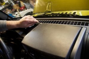
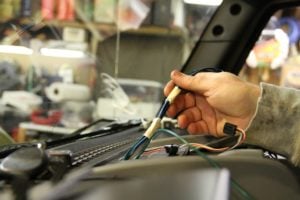
To begin the installation, we will remove the top panel on the center stack where our new gauges will ultimately reside. As we have done here, you will start at the very back corner as the front edge loops around the bottom.
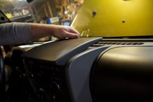
Slowly work your way around the back while pulling up gently towards you. This should not require any significant amount of force.
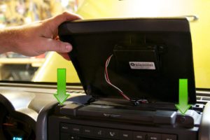
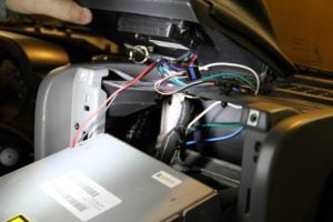
Once we have got the cover up, we see the Jeep’s compass module is placed underneath. There are two bolts you will want to remove to get the center stack trim free. The red and yellow wire to the module is a great place to grab keyed power for the gauges and the black wire will supply a good ground for the lights (not for the gauges though, as we will go over later).

The bolts require a 7mm socket.
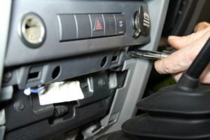
Pry the bottom trim piece free by starting from the top and prying towards you. Then, there are two more 7mm bolts on the bottom you will find.
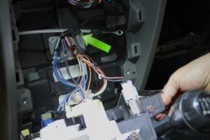
With the four bolts removed, the center stack trim can be pulled free. The HVAC head on this vehicle uses the old school cable style adjustments. You will need a small screwdriver to release the lock tabs on the two rings (the arrow shows the tab and direction you’ll need to press). We also pulled the radio at this point so we have more room. This is simply four 7mm screws.
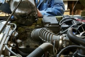
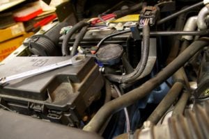
With access to the interior taken care of, we get to work under the hood. We will need some more room here, so we will remove the airbox. After disconnecting the air outlet hose to the engine, this one is very simple and just pulls straight up.
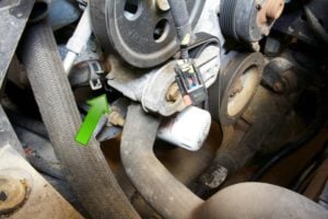
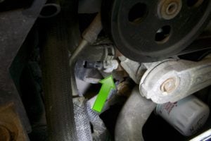
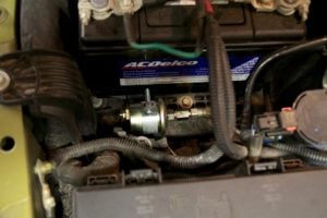
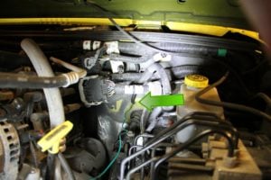
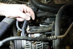
The best spot we could find to access the oil was the factory switch location right behind the belt tensioner. It’s tough to see. The loose connector in the picture is the one we removed from the switch.

You will want an oil pressure switch socket to get the switch out. Your local auto parts store should have one.
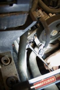
There’s not a great deal of room to maneuver a ratchet, but patience is rewarded.
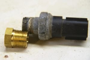
Once the switch was out, we compared it to the thread adapters that came with our gauges and found it to be a 3/8″ NPT thread.
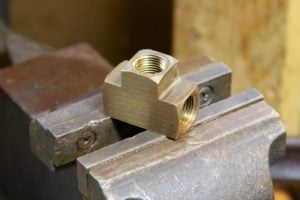
We were uncertain if the computer used the switch signal for anything other than the indicator light, so we decided to play it safe and retain the factory switch via the use of a 3 x 3/8″ NPT tee fitting that we picked up at the local hardware store.
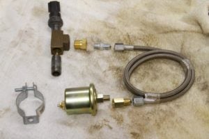
In order to provide adequate clearance for the sender, we thought it best to remote mount the sending unit using an AutoMeter Part #3227 braided line kit. In this picture, you can see our group of parts. The only items in this picture that wouldn’t be included in the kits is a 3/8″ NPT male to male extension piece (close nipple), the 3/8” NPT T fitting, and a 1 1/2″ conduit hanging bracket we also acquired while at the hardware store. We later had to get an AutoMeter Part #3273 angle fitting which you will see a few slides from here. You will want to use liquid Teflon (not tape) on the NPT fittings, but leave the -AN fittings bare.
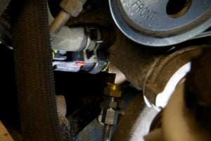
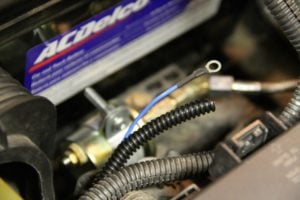
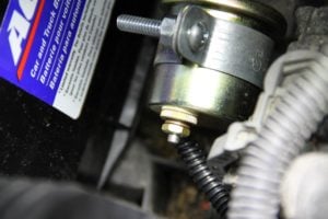
We start by installing the extension, tee and factory switch. We tightened until the empty port on the side of the T fitting was orientated in such a way that we had clearance to install the AutoMeter Braided Hose Kit. You can see this orientation with the empty port pointing downward, just behind the tensioner.
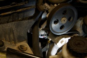
Here is a shot of the whole assembly in place, and the hose kit connected to the T fitting.
Now, we will add the line kit to the bottom. You will want to be aware of the angle that your tee fitting sits at, as we don’t want to risk contact with the motor mount bracket when the engine rocks back and forth.

We now route our braided stainless hose back and away from the serpentine belt. We chose to zip tie along the coolant hose in the picture to keep it secure.
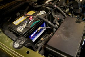
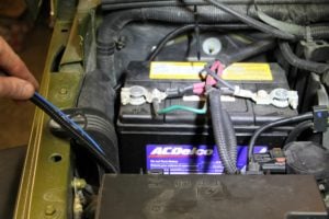
With the line secured, we routed it behind the power distribution box into a nice open area in front of the battery.
After getting everything in place, we realized a 45-degree fitting would relieve tension from the setup and give us the long-term reliability that we are after. We used the AutoMeter Part #3273 in this case.
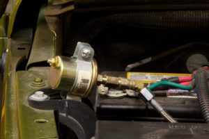
Here is the sender with all the fittings and the conduit bracket installed. We drilled a small hole in the plastic tray in front of the battery.
Then, we tightened the sender in place.

With that out of the way, we decided to wire up the gauges. We put all the powers together, the ground together, the light power together and the light grounds together. The gauge and light grounds are separate for good reason. Tying these together could lead to your gauges reading inaccurately. It’s very important that these are not tied together.
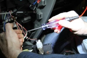
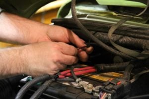
We wanted our gauge lights to work with the factory dimmer switch. We consulted ALLDATA and found the orange wire with the grey stripe coming out of the HVAC control head to be the right place to go. After judging where we would be splicing on, we did a quick test to verify functionality. While we are normally completely against the use of test lights, this is one instance where it actually is the right tool for the job. The light became dimmer and brighter with the switch, verifying what the wiring diagram had told us.
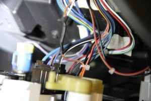
Here is the white lighting wire from the gauges in place on the orange/grey dimmer wire.

Since this vehicle was a 6 speed, we couldn’t simply poke through the hole where the clutch pedal cable should be on most cars. After some poking around, it became evident some drilling would be necessary. Since the only drill we had on hand was gigantic, we had to go from the engine side of the firewall. We chose this spot right next to the steering shaft. This photo shows the bit peeking through from the interior side.
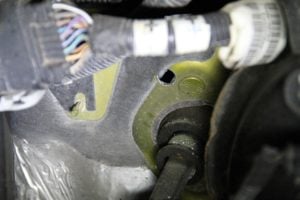
Here is the exact spot we chose from the engine side of the firewall.
We then taped our two sender wires and our gauge ground wires to a giant zip tie to make threading through the dash easy. Once through, we added split conduit wire sheathing to protect them.
With the wires run through the dash, we were able to put the radio back in place and set the cover with the gauges down.

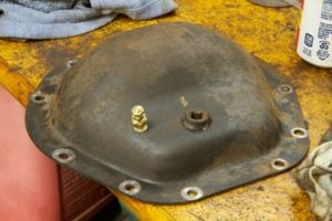
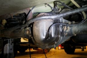
We then pulled the differential cover to prepare for sensor installation. It is worth noting that the Dana 44 in this vehicle uses a synthetic 75w140 gear oil. We found this at our local auto parts store.
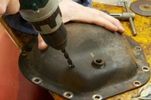
We then take a 5/16″ drill bit and went to town on the world’s thickest diff cover. It’s worth noting that we are indeed below the fill plug and away from where the ring gear would reside.
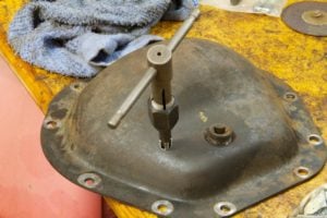
We then took a 1/8″ NPT pipe tap to the hole with a little assembly lube. You don’t want to run the tap all the way down. Start by going about halfway down and then test the fit with the sender.
As with the oil pressure sender, always use liquid Teflon with the NPT threads on the sending unit.
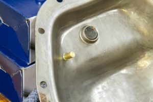
You will know you have it tapped correctly when you see one thread poke through the other side.

As the axle normally doesn’t have a good path to common ground on the vehicle, we added a supplemental ground wire to ensure an accurate gauge reading, as the gauge sender must be threaded into something that is grounded. We used a thick 10 gauge wire with lots of slack to allow for suspension travel.
Now, we will start to clean up the wiring by adding a thick rubber grommet to the hole to protect it and some split tube conduit.

We routed the oil pressure sender wire along the firewall and zip tied it to existing the conduit.
Here’s where we made the turn to the sender.
We threaded it in under this plastic tray.
We added ring terminals to our wiring for a good connection on the senders.
Here is the oil pressure sender, all buttoned up.
Earlier, we had mentioned that the ground wire would need to go through the firewall as well. The gauges do their measurements along the ground side of the circuit, so a good ground is the most crucial step for an accurate gauge. We normally recommend going directly to the engine block. As the valve cover bolts went through rubber and the intake was phenolic, we chose this bracket as the best possible ground on the motor.
We then routed the axle temp sender wiring along a brake line to keep it clear of the exhaust and possible obstacles along the trail. You’ll notice a loose zip tie there just to act as support while the axle moves around. We also shot it with a quick blast of paint to protect against corrosion here in the salt belt.

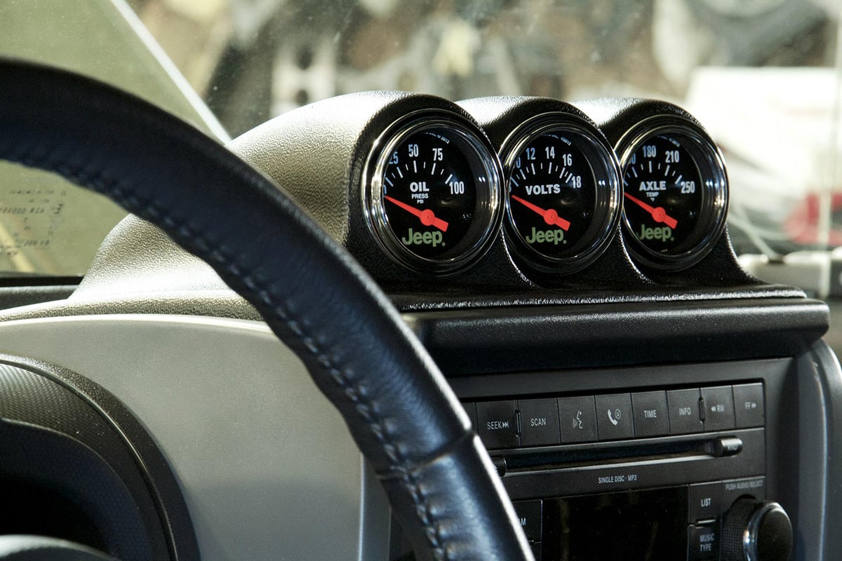
Here’s the finished product. You can see how perfect the fit is on the pod. This pod is a Direct Fit Dash Top from AutoMeter, which is Part #5380.

And one last shot of our results. Perfect factory fit.
Make sure your vehicle will make it safely back to the pavement and ensure the long life of your vehicle with AutoMeter’s Jeep Gauges.
Part Used
- Voltmeter Gauge – Part #880242
- Axle Temperature – Part #880431
- Oil Pressure – Part #880240
- Direct Fit Dash Top Pod – Part #5380
- Adapter Fitting – Part #3273
- Braided Line – Part #3227
- 3/8”NPT T-Fitting
- 3/8”NPT Close Nipple
- Various Zip Ties, Electrical Terminals, and various lengths and colors of 20g stranded wire